
For this assignment we had to analyse the power usage data of Avans University and create a physical installation.
The concept
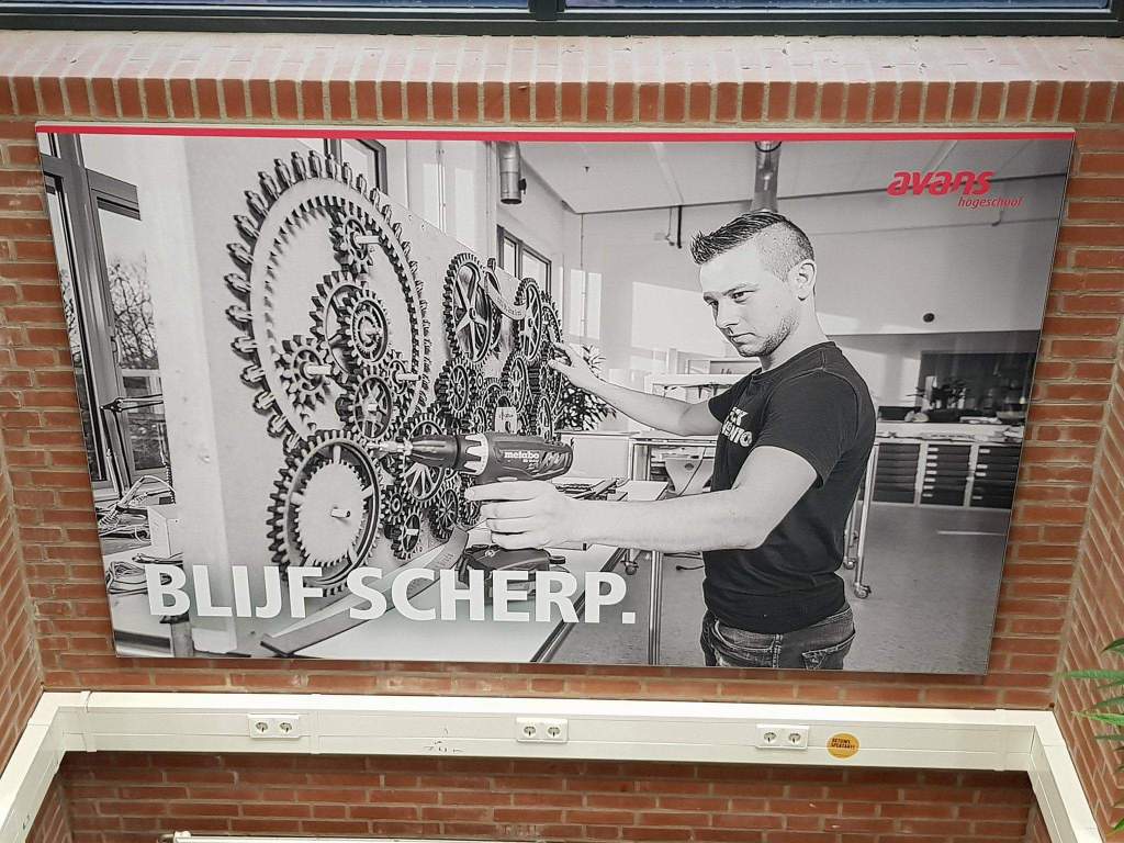
Avans University of Applied Sciences is a Dutch high ranked university and has multiple buildings in four cities and 13 locations: Breda, ‘s-Hertogenbosch, Tilburg, and Roosendaal. The university has 35,000 students studying 61 courses in 18 institutes. There are 3,300 employees.
As you can see Avans University is an enormous company, with a lot of different sub-sections all part of the bigger organisation. This organisation is putting a lot of effort in making its buildings durable, and energy efficient to save on the electricity and gas bills.
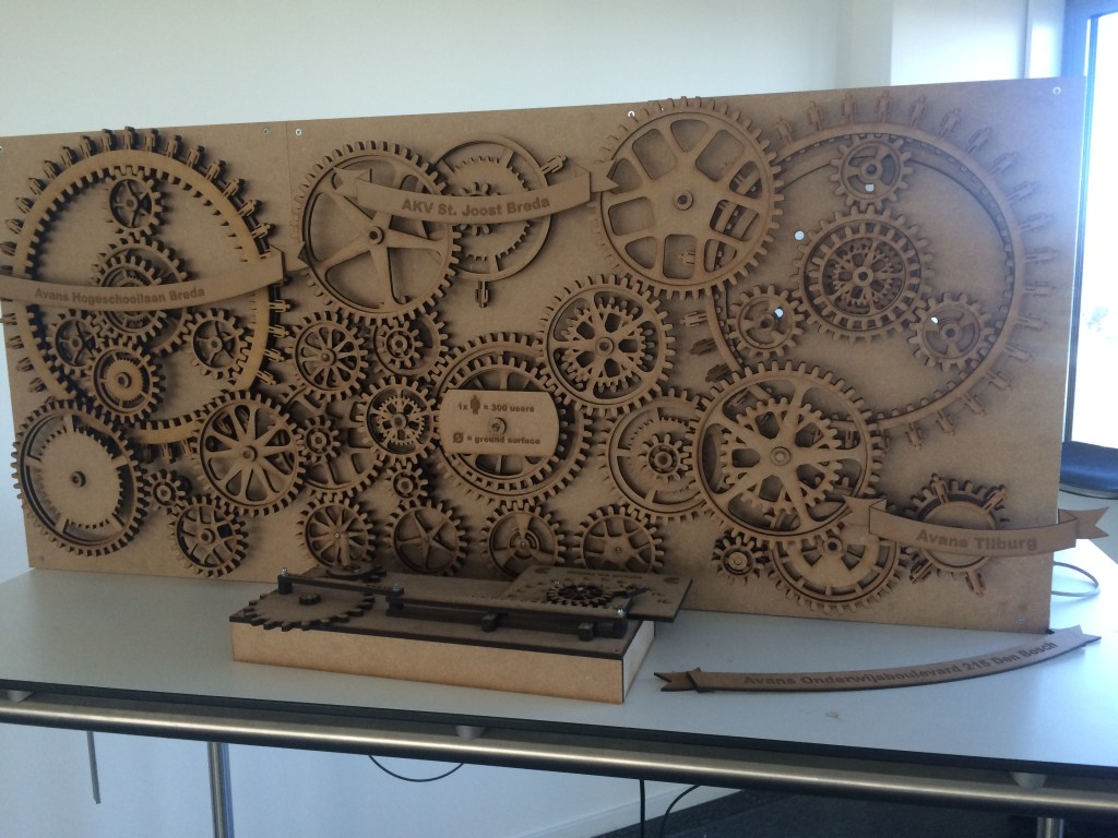
We were asked to investigate, and visualise our insights. We wanted to show the correlation between the density of people in different buildings, the building sizes and energy usage of the different buildings. We wanted to show these three aspects in an interactive ‘machine’.
The appearance
We wanted the installation to be interactive, and came up with the idea of making money the input: As different buildings had different costs per user (students and employees), we wanted to show this in a manner that would also take in account the size of the buildings, and let users of our installation play with to find interesting relations between the size of the buildings, the users they hold and the costs of electricity.
The input
We brainstormed frequently how to shape the input: money. At first we wanted to use printed coins, which the users could insert in to the installation. Even though this would properly visualise that the users are dealing with money, it had some downsides to it.
- It wouldn’t be monkey proof in a exhibition setup;
- Feedback about the amount of money already in the installation would be difficult to build within the timeframe;
- Removing coins would be difficult, while the focus was on users to explore and play with the amount of input.
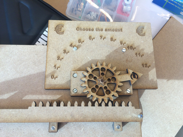
Each individual point needed to be solved in order to make the interaction work. Due to time constraints on this project we had to devise a system that could imitate the use of money without actually having to produce a working coin operation. We settled on a physical slider/ gauge, that would solve all the above issues. The appearance of the slider wasn’t important at this stage.
The physical slider was not the best feature, but it was effectively a reliable bug-free input controller.

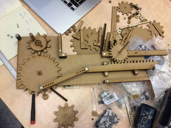
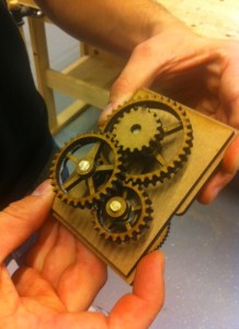
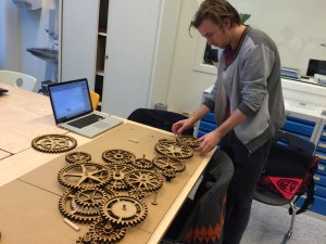
Prototyping
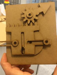
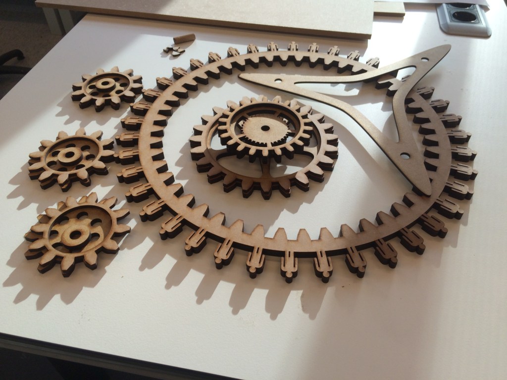
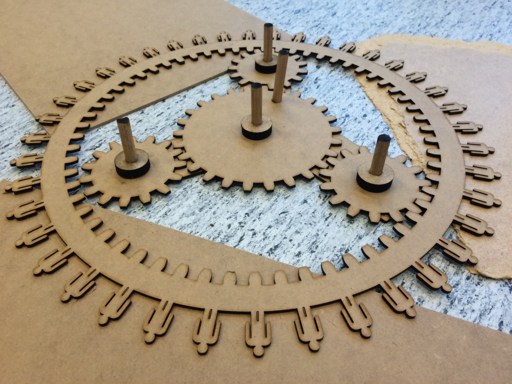
I’ve created small versions of gears, even though we couldn’t test the friction of a big installation, we got an idea of how the installation would look. Furthermore, we learned how to layer the gears, with different thicknesses of wood and having wooden bearings in between the double layered gears so we could change gear ratios.
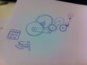

Analysing data
The first concept involved lightbulbs which would turn on whenever the price of running a building was reached. While we were designing the different gears in all kinds of sizes, we realised that we could do much more with the gears themselves. Gears have a lot of attributes to be able to pass on data, such as the size, number of teeth, thickness, speed, direction, etc. Why not create gears to represent the different schools, instead of lightbulbs?
Instead of what we wanted to show first, which was:
- The electricity costs per user per month for an Avans building (durability of a building)
We now gave the user other data, so the user could see the relationship between the building size and occupancy and energy use, from which they could draw conclusions from our installation. We now had the following aspects we could show:
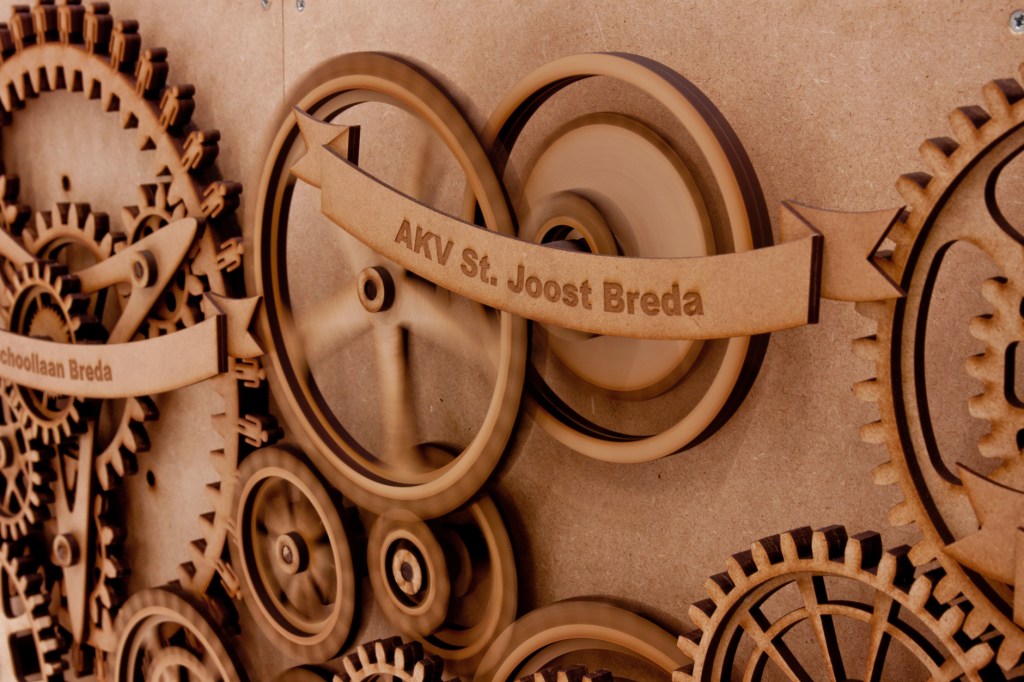
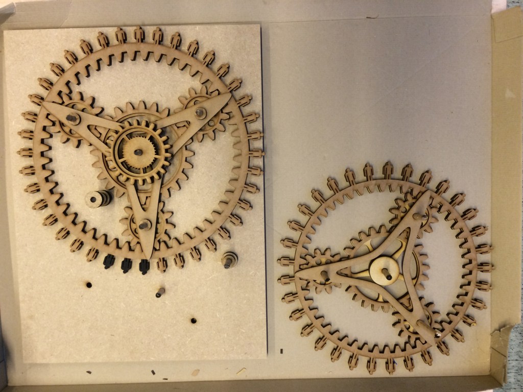
- The size of an Avans building (size of it’s gear)
- The amount of users of an Avans building (the gears have no teeth but little men)
- Density of users (spacing between the men)
- Amount of students (not-engraved men)
- Amount of employees (engraved men)

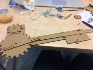
Scaling up
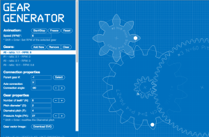
We used the online tool: geargenerator.com. This took a lot of calculating out of our hands, as all the different sizes of gears needed to have the same amount of teeth, with the same size, and the same spacing at the same angle.
Let the lasercutting begin!

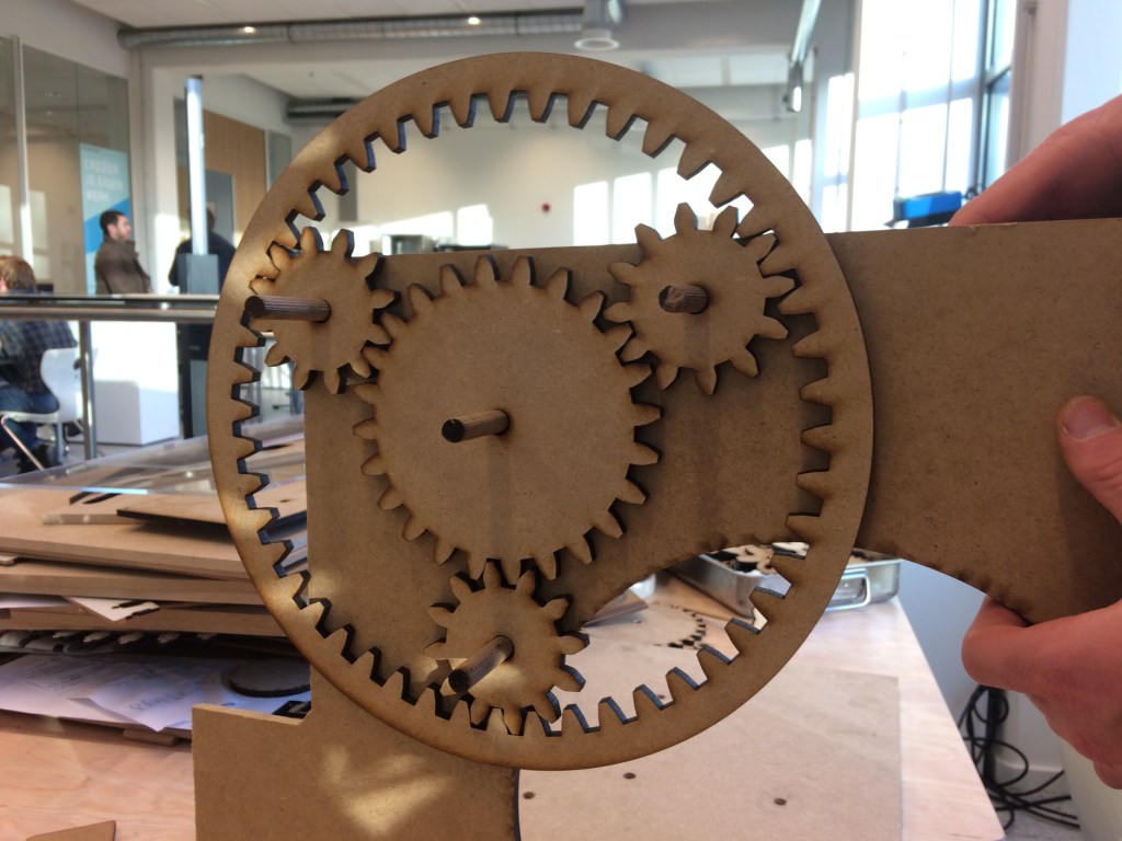
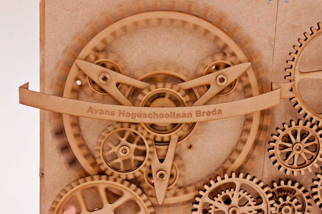
The planetary gears
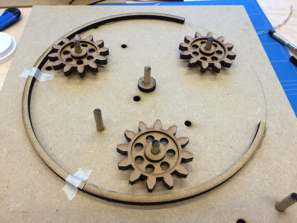
The first prototypes: It worked, but the teeth did not have an optimal shape, especially the inner teeth of the ring-gear. Also, there was too much spacing between the gears. We tested the whole installation lying down, and later came to the conclusion these flaws were a big problem when the installation was standing upright.
We had to redo the planetary gears. We found the correct amount of teeth on each gear to be:
Ring = 2*Planet + Sun (in our case: 60 = 2*24 + 12)
I manually designed each of the gears to meet this criteria, retouched the shape of the teeth and minimised the spacing. This was a huge improvement. Still, issues arose when putting the installation together. As the ring-gear is not attached to the frame, it wiggles on the upper planet-gear. I tried hanging the ring-gear on two planetary gears, with a little improvement.
This still wasn’t enough of a solution, so I designed a way to gently press the ring-gear on a round ring on the backplate, just enough to keep the ring from wiggling, while minimising movement resistance on the backplate.
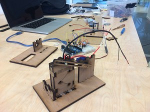
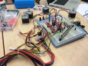
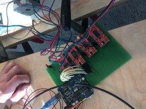
The electronics
We had to figure out the electronics that we needed to build our installation, and put it all together on a breadboard. There’s not much to say, it’s just putting wires in the right slots. The coding is what it is all about. I designed it all on a PCB. It was now a lot smaller and the drivers could easily be replaced if necessary.
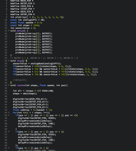
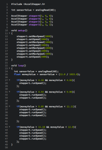
The code
Controlling stepper motors was not the easiest task, because of the way they work. They do not work with speed, or on and off as a servomotor. To control it, you tell it to quickly change polarity of magnets in the motor to make it do one step. If you want to control two motors, code loops through a step at a time per motor, but as it takes twice as long, the motors will rotate twice as slow.
We had difficulty in mastering the code, and we really didn’t know what we were doing (right or wrong).
There are a lot of stepper libraries out there on the internet that make controlling steppers easier, but none of them support controlling multiple steppers simultaneously with a motor shield. Eventually we found one that worked with our shields, and as you can see, that made the code a whole lot easier.
Assembly
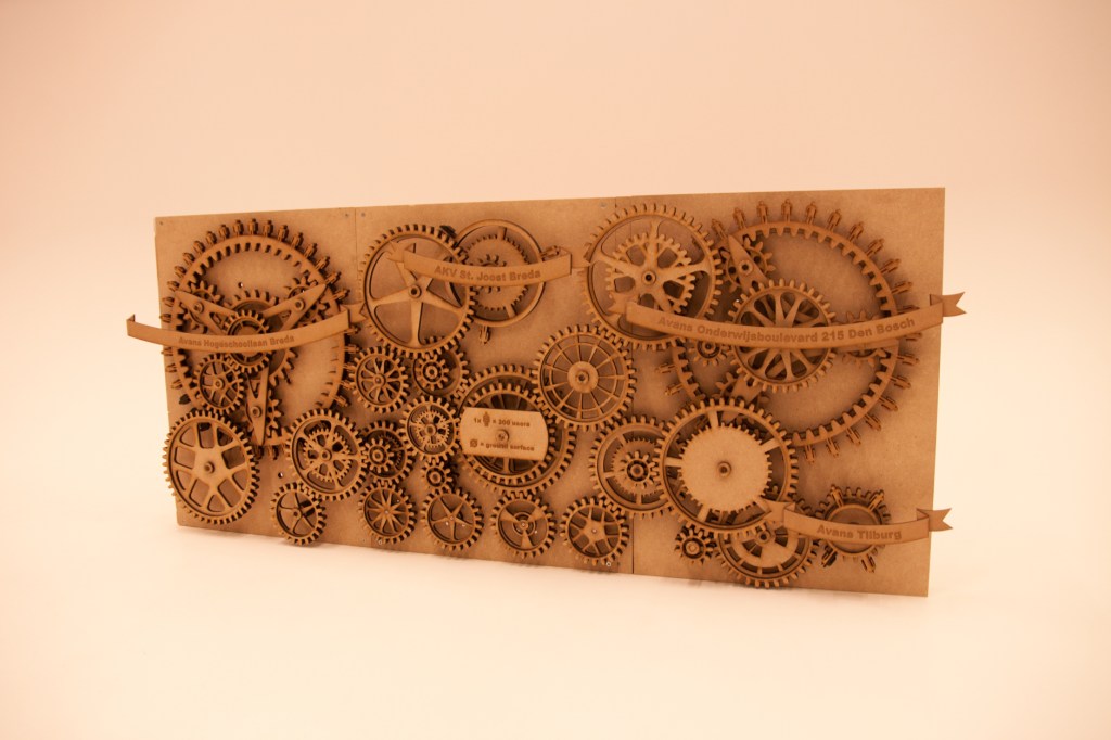
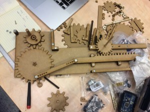
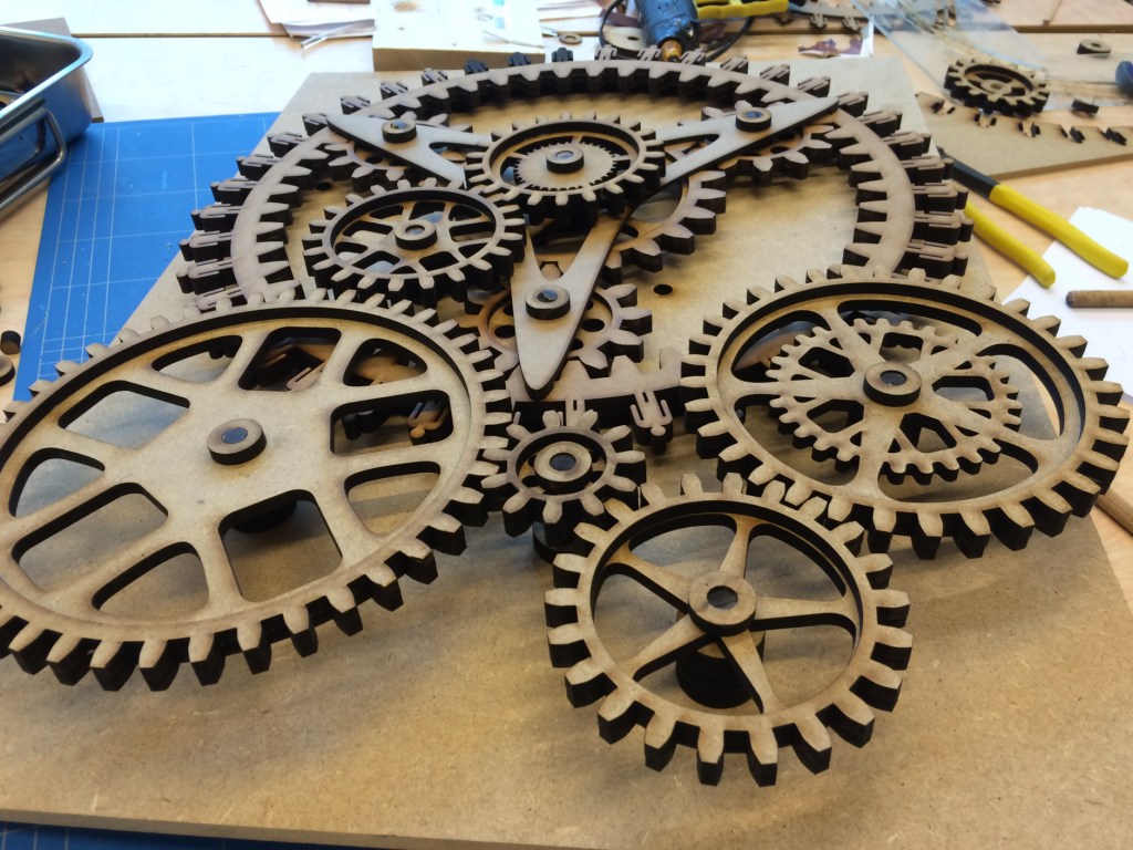
After a lot of fine tuning to get the right size, the position and design of the gears it was time to put it all together.
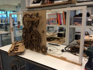
The result